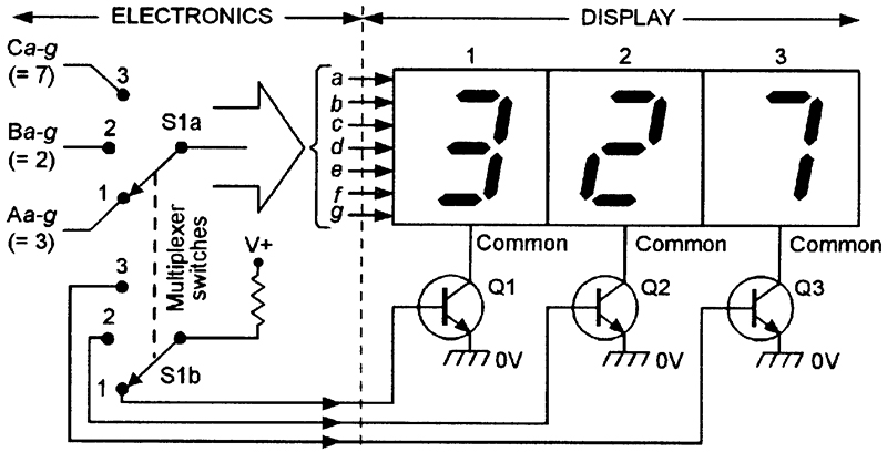
Set up a 4 byte area of memory that contains a bitmap of the desired LED states and use that to communicate with the ISR (your program writes to it and the ISR only reads it). It is best to do this in a timer interrupt routine, though it's fine to test it with simple-minded delays- but that will use up 100% of the MCU cycles. By bringing the Q1-Q4 high while the C1.C7 are changing you avoid "ghosting" (dimly lit unwanted segments). Also invert the state to high=ON, of course.įirmware wise, the algorithm is to start with all 4 drives to Q1-Q4 high (off), set the GPIOs corresponding to C1.C7 LOW for each LED out of 7 you want to have "on", bring the drive for Q1 LOW, hold for perhaps 250-1000usec, then bring all Q1-Q4 high again, set up for Q2 and repeat. If that does not yield sufficient brightness you could add a ULN2003A or 7 MOSFETs to the 7 resistors, however you would have to recalculate the resistor values to yield the higher current and take into account the relatively high drop of the Darlington transistors into the ULN2003A. If your LED has a Vf of 2.0V (green or yellow) that's about 200 ohms.

You pick RXi to yield the peak current of 14.3mA, so about (4.8V-Vf)/0.0143. You would pick RSi to yield about 1/20 of the 100mA total LED current through the transistor base, so about 5mA. With this circuit you are driving the entire display current through the MCU ground pin so you are limited to an absolute maximum of 200mA, and you should stay well away from that, so let's assume 100mA total current (meaning an average LED current per LED of only 3.6mA and a peak LED current of 14.3mA) Simulate this circuit – Schematic created using CircuitLab


The easiest way to drive this multiplexed display is like this (although the designation is K, what you have is driven the same as a 4-digit common Anode numerical LED display):


 0 kommentar(er)
